Hyundai Elantra (CN7): Intake And Exhaust System / Air Cleaner
Components and components location
| Components |
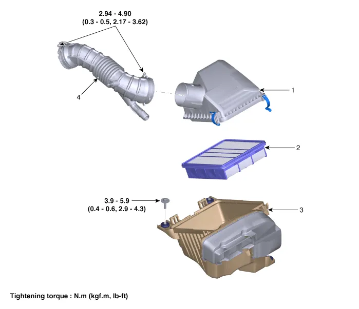
| 1. Air cleaner cover 2. Air cleaner element | 3. Air cleaner body & air duct 5. Air intake hose |
Repair procedures
| Removal and Installation |
Air Cleaner Assembly.
| 1. | Disconnect the battery negative terminal. |
| 2. | Disconnect the breather hose (A).
|

| 3. | Disconnect the RCV hose (A).
|

| 4. | Disconnect the air intake hose (A), and then remove the air cleaner assembly (B).
|


| 5. | Install in the reverse order of removal. |
Air Cleaner Element Replacement
| 1. | Open the air cleaner cover by unhooking the clamps (A).
|

| 2. | Replace the air cleaner element (A) with a new one.
|

| 3. | Close the air cleaner cover by hooking the clamps.
|

Components and components location Components1. Electronic throttle body (ETC)2. Return hose3. Return pipe4. Intake manifold5. Intake manifold gasket Repair procedures Removal and Installation1.
Other information:
Hyundai Elantra (CN7) 2021-2026 Service Manual: Auto Lighting Control System
Description and operation DescriptionIt's a system that uses illumination sensor to automatically turn ON the tail lamp and head lamp based on the change in surrounding environment's illumination condition. It activates when the vehicle enters/exits tunnel, or when the illumination condition in surrounding environment changes due to rain, snow, or
Hyundai Elantra (CN7) 2021-2026 Service Manual: Components and components location
C
Categories
- Manuals Home
- Hyundai Elantra Owners Manual
- Hyundai Elantra Service Manual
- Front Radar Unit
- Engine Mechanical System
- Instrument Panel Overview
- New on site
- Most important about car

Copyright © 2026 www.helantra7.com - 0.0163