Hyundai Elantra (CN7): Vehicle Information / Interior Overview
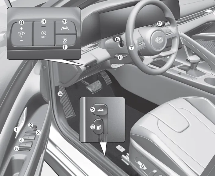
1. Inside door handle
2. Side view mirror control switch
3. Central door lock switch
4. Power window switches
5. Power window lock button
6. Steering wheel tilt/telescopic lever
7. Steering wheel
8. Instrument panel illumination control
switch
9. ISG (Idle Stop & Go) OFF button
10. Lane Safety button
11. ESC OFF button
12. Fuel filler door release lever
13. Trunk release lever
14. Hood release lever
15. Light control/Turn signals
16. Seat adjusting switch
17. Wiper/washer switch
Front view 1. Hood 2. Headlamp 3. Tires and wheels 4. Side view mirror 5. Sunroof 6. Front windshield wiper blades 7. Windows 8. Front radar Rear view 9.
1. Instrument cluster 2. Driver’s front air bag 3. Engine start button 4. Key ignition switch 5. Infotainment system 6. Hazard warning flasher switch 7.
Other information:
Hyundai Elantra (CN7) 2021-2026 Service Manual: A/C Pressure Transducer
Description and operation DescriptionThe A/C Pressure Transducer (APT) converts the pressure value of high pressure line into voltage value after measuring it. By converted voltage value, engine ECU controls the cooling fan by operating it high speed or low speed.
Hyundai Elantra (CN7) 2021-2026 Service Manual: Rear Corner Radar Unit
Specifications Specifications Items Blind-Spot Collision Warning (BCW) Blind-Spot Collision- Avoidance Assist-Rear (BCA-R) Rated voltageDC 12VOperating voltage9V - 16VOperating speed30 km/h - 255 km/h60 km/h - 180 km/hSensible distance70m Curvature radiusStart : More
Categories
- Manuals Home
- Hyundai Elantra Owners Manual
- Hyundai Elantra Service Manual
- Body Electrical System
- Engine Control / Fuel System
- Front Bumper
- New on site
- Most important about car
