Hyundai Elantra (CN7): Vehicle Information / Instrument Panel Overview
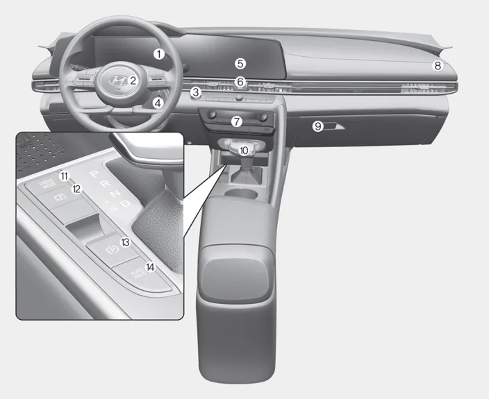
1. Instrument cluster
2. Driver’s front air bag
3. Engine start button
4. Key ignition switch
5. Infotainment system
6. Hazard warning flasher switch
7. Climate control system
8. Passenger’s front air bag
9. Glove box
10. Manual transmission/
Intelligent variable transmission
11. Drive mode button
12. Parking/View button
13. Electronic parking brake switch
14. AUTO HOLD button
1. Inside door handle 2. Side view mirror control switch 3. Central door lock switch 4. Power window switches 5. Power window lock button 6. Steering wheel tilt/telescopic lever 7.
Smartstream G 2.0 Atkinson 1. Engine coolant reservoir 2. Brake fluid reservoir 3. Air cleaner 4. Engine oil dipstick 5. Engine oil filler cap 6.
Other information:
Hyundai Elantra (CN7) 2021-2026 Service Manual: Temperature Control Actuator
Description and operation DescriptionThe temperature control actuator is located at the heater unit. It regulates the temperature by the procedure as follows. The signal from the control unit adjusts the position of the temperature door by operating the temperature switch.
Hyundai Elantra (CN7) 2021-2026 Service Manual: Mode Control Actuator
Description and operation DescriptionThe mode control actuator is located at the heater unit.It adjusts the position of the mode door by operating the mode control actuator based on the signal of the A/C control unit. Pressing the mode select switch makes the mode control actuator shift in order of Vent → Bi-Level → Floor → Mix.
Categories
- Manuals Home
- Hyundai Elantra Owners Manual
- Hyundai Elantra Service Manual
- Driver assistance system
- Engine Control / Fuel System
- Body Electrical System
- New on site
- Most important about car
