Hyundai Elantra (CN7): Clutch System / Ignition Lock & Clutch Switch
Description and operation
| Description |
| – | Clutch operation is detected through clutch switch signal. This signal enables ECM to cope with instant change of load condition. |
| – | Clutch switch signal is used to detect engaged gear with vehicle speed and engine speed. |
Schematic diagrams
| Connector and Pin Function |
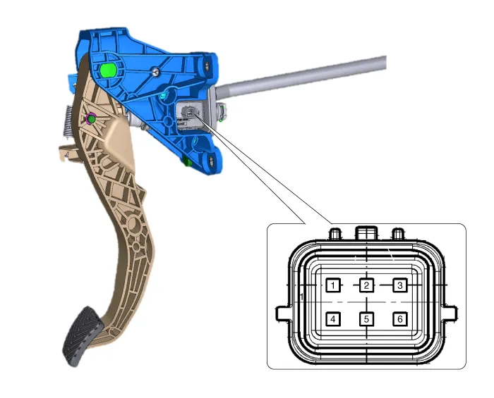
| Connector |
|
Terminal
|
Description
|
| 1 | IG1 |
| 2 | Clutch switch |
| 3 | Ignition lock switch |
| 4 | Battery + |
| 5 | PWM signal |
| 6 | Ground |
Repair procedures
| Replacement |
|

Repair procedures Removal1.Remove the manual transaxle assembly.(Refer to Manual Transaxle System - "Manual Transaxle")2. Remove the clutch cover assembly after loosening the bolts.
Components and components location Components1. Clutch pedal arm2. Clip3. Push rod pin4. Clutch pedal assembly5. Clutch master cylinder6. Clip Repair procedures Removal1.
Other information:
Hyundai Elantra (CN7) 2021-2025 Service Manual: Head Lamp Leveling Switch
Schematic diagrams Schematic Diagrams Repair procedures Replacement1.Disconnect the negative (-) battery terminal.2.Remove the crash pad lower panel (A).(Refer to Body - "Crash Pad Lower Panel")3.Loosen the mounting screw and remove the crash pad lower switch (A).
Hyundai Elantra (CN7) 2021-2025 Service Manual: General safety information and caution
General Safety Information and Caution1.Be careful when driving the vehicle using the smart cruise control system as follows.(1)On curves or inclines/declines• The smart cruise control system may have limits to detect distance to the vehicle ahead due to road and traffic conditions.
Categories
- Manuals Home
- Hyundai Elantra Owners Manual
- Hyundai Elantra Service Manual
- Clutch System
- Towing
- Heating, Ventilation and Air Conditioning
- New on site
- Most important about car
