Hyundai Elantra (CN7): Body (Interior and Exterior) / Front Bumper
Components and components location
| Components |
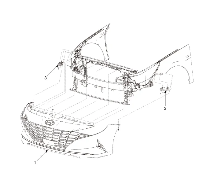
| 1. Front bumper assembly 2. Front bumper side bracket [LH] | 3. Front bumper side bracket [RH] |
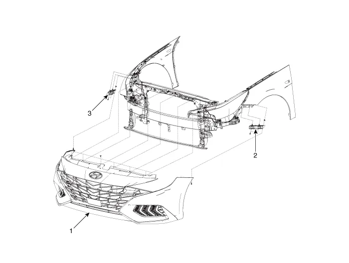
| 1. Front bumper assembly 2. Front bumper side bracket [LH] | 3. Front bumper side bracket [RH] |
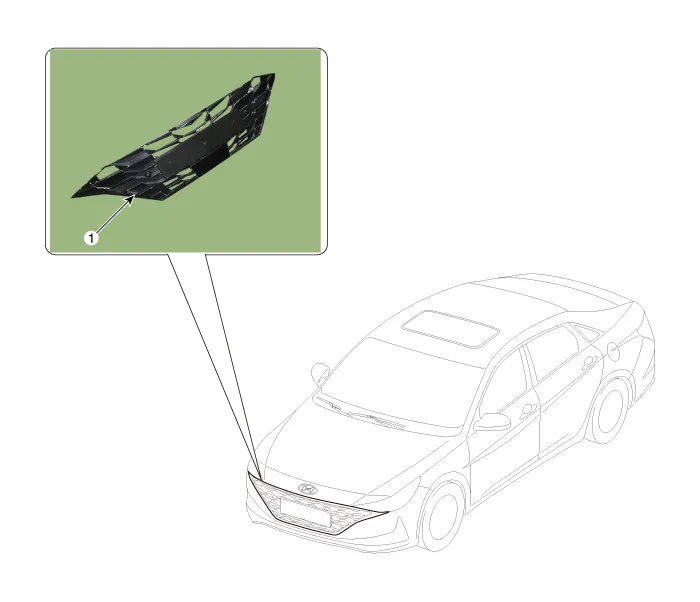
Front Bumper Assembly
Components and components location
| Component Location |
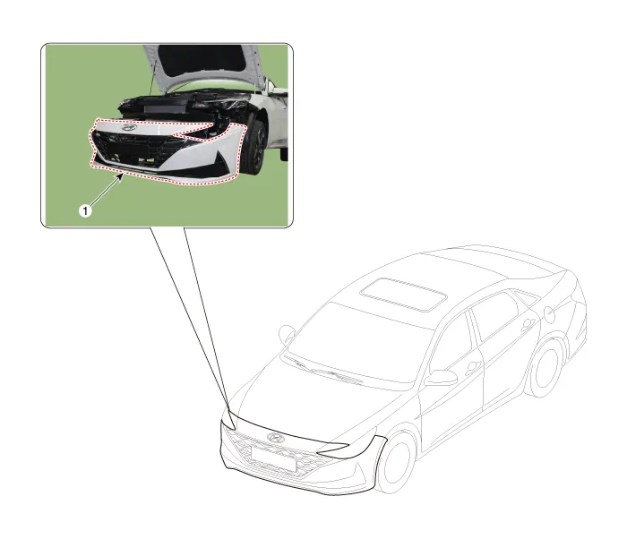
| 1. Front bumper Assembly |
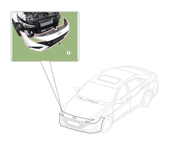
| 1. Front bumper assembly |
Repair procedures
| Replacement |
|

|

| 1. | Loosen the front bumper upper mounting clips.
|

| 2. | Loosen the front bumper lower mounting clips.
|

| 3. | After loosening the pin-type retainers and screws on the side of front bumper (A), detach the side part of front bumper.
|


| 4. | Disconnect the front bumper main connector (A).
|

| 5. | Remvoe the front bumper assembly (A). [General type]
[N Line]
|


| 6. | To install, reverse the removal procedure.
|

Radiator Grill
Components and components location
| Component Location |
| 1. Radiator grill |
Repair procedures
| Replacement |
|
|
| 1. | Remove the front bumper assembly. (Refer to Front Bumper - "Front Bumper Assembly") |
| 2. | Detach the wiring (A) mounted on the front bumper assembly and energy absober.
|

| 3. | Remove the front bumper energy absorber (A).
|

| 4. | Loosen the mounting screws, remove the radiator grill (A).
|

| 5. | To install, reverse the removal procedure.
|
|
|
| 1. | Remove the front bumper assembly. (Refer to Front Bumper - "Front Bumper Assembly") |
| 2. | Detach the wiring (A) mounted on the front bumper assembly and energy absober.
|

| 3. | Remove the front bumper energy absorber (A).
|

| 4. | Loosen the mounting screws, remove the radiator grill upper cover (A).
|

| 5. | Remove the front bumper lip (A).
|

| 6. | Loosen the mounting screws, remove the front bumper grill (A).
|

| 7. | Loosen the mounting screws, remove the front bumper molding (A).
|

| 8. | Loosen the mounting screws, remove the radiator grill (A).
|

| 9. | To install, reverse the removal procedure.
|
Repair procedures Replacement • When removing with a flat - tip screwdriver or remover, wrap protective tape around the tools to prevent damage to components.
Components and components location Component Location [General type]1. Rear bumper assembly2. Rear bumper under cover [LH]3. Rear bumper under cover [RH]4.
Other information:
Hyundai Elantra (CN7) 2021-2026 Service Manual: Description and operating principle
Description and OperationWireless Power Charger SystemDuring ACC or IG ON, battery voltage is supplied to the wireless power charger system to transmit an output of 5 W to mobile phone. Mobile phones certified with the wireless charging standard WPC (Qi 1.
Hyundai Elantra (CN7) 2021-2026 Service Manual: Troubleshooting
TroubleshootingProblem Symptoms TableBefore replacing or repairing air conditioning components, first determine if the malfunction is due to the refrigerant charge, air flow or compressor.Use the table below to help you find the cause of the problem. The numbers indicate the priority of the likely cause of the problem.
Categories
- Manuals Home
- Hyundai Elantra Owners Manual
- Hyundai Elantra Service Manual
- Front Bumper
- Front Radar Unit
- Recommended Lubricants and Capacities
- New on site
- Most important about car
