Hyundai Elantra (CN7): Button Engine Start System / Start/Stop Button
Components and components location
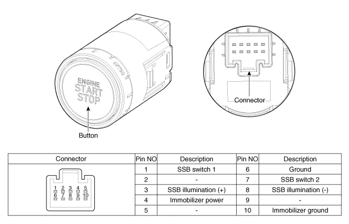
| Component |
Repair procedures
| Removal |
| 1. | Disconnect the negative(-) battery terminal. |
| 2. | Remove the AVN Head unit. (Refer to Body Electrical System - "AVN(Audio Video Navigation) head unit") |
| 3. | Loosen the mounting screws and remove the start/stop button (A).
|

| Installation |
| 1. | Install the start/stop button. |
| 2. | Install the AVN head unit. |
| 3. | Connect the negative (-) battery terminal. |
Component Location1. Smart key unit (IBU)2. Interior antenna 23. outside door handle4. Interior antenna 15. FOB Key6. Door antenna1. Bumper antenna2. Trunk antenna
Other information:
Hyundai Elantra (CN7) 2021-2026 Service Manual: Wireless Power Charging Unit
Components and positions Components Circuit diagram Circuit Diagram Repair procedures Removal • Handling wireless charging system parts by wet hands may cause electric shock. 1.Disconnect the negative (-) battery terminal.
Hyundai Elantra (CN7) 2021-2026 Service Manual: Repair procedures
Refrigerant System Service Basics (R-134a)Refrigerant Recovery Use only service equipment that is U.L-listed and is certified to meet the requirements of SAE J2210 to remove HFC-134a(R-134a) from the air conditioning system. • Air conditioning refrigerant or lubricant vapor can irritate your eyes, nose, or
Categories
- Manuals Home
- Hyundai Elantra Owners Manual
- Hyundai Elantra Service Manual
- Specifications
- Maintenance
- Integrated Thermal Management Module (ITM)
- New on site
- Most important about car
