Hyundai Elantra (CN7): Manual Transaxle System / Manual Transaxle
Components and components location
| Components |
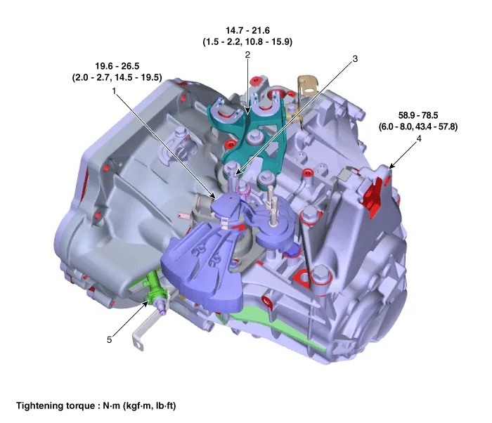
| 1. Control shaft complete 2. Control cable bracket 3. Back-up lamp switch | 4. Manual transaxle bracket 5. Concentric slave cylinder |
Repair procedures
| Removal |
| 1. | Remove the air cleaner assembly and air duct. (Refer to Engine Mechanical System - "Air Cleaner") |
| 2. | Remove the battery and battery tray. (Refer to Engine Electrical System - "Battery") |
| 3. | Loosen the bolt and then separate the engine wiring (A).
|

| 4. | Disconnect the back up lamp switch connector (A).
|

| 5. | Remove the control cable bracket and control cable at the same time.
|


| 6. | Loosen the bolt and then separate the ground line (A).
|

| 7. | Remove the snap pin (A) and the clutch hose (B).
|

| 8. | Remove the starter motor mounting bolts (A) and the transaxle upper mounting bolts (B).
|

| 9. | Assemble the engine support fixture use a (Beam SST No.: 09200 - 3N000, Adapter SST No.: 09200-4X000, Engine fixture adapter (rear) SST No.: 09200-L1100, Engine fixture adapter (front) SST No.: 09200-L1200. |
| 10. | Using the engine support fixture(A), hold the engine and transaxle assembly safely.
|

| 11. | Remove the dust cover (A).
|

| 12. | Loosen the transaxle bracket support mounting bolts (A).
|

| 13. | Loosen the bolts and then removing the transaxle bracket (A).
|

| 14. | Remove the under cover. (Refer to Engine Mechanical System - "Engine Room Under Cover") |
| 15. | After loosening the drain plug (A), drain the manual transaxle fluid, then install the drain plug.
|


| 16. | Loosen the bolts and then removing the wiring bracket (A, B).
|


| 17. | Loosen the bolts (A, B) and then removing the roll rod assembly (C).
|

| 18. | Loosen the bolts and then removing the roll rod support bracket (A).
|

| 19. | Remove the drive shaft assembly. (Refer to Driveshaft and axle (2WD-FF) - "Front Driveshaft") |
| 20. | Remove the lower mounting bolts (A), (B) of lower part of the transaxle, and the left side cover and remove the transaxle assembly by supporting it with a jack.
|

| Installation |
|


| 1. | To install, reverse the removal procedures. |
| 2. | Injection the manual transaxle fluid. (Refer to Manual Transaxle System - "Manual Transaxle Fluid") |
| 3. | Perform bleeding air procedure in concentric slave cylinder after pouring the brake fluid. (Refer to Clutch System - "Repair Procedures") |
General information General Information1.Check & Change intervals Check & Replenishment Change Capacity Oil specification Normal use Severe Use 60,000 km / 4 years(40,000 miles / 4years)No service required120,000 km(80,000 miles)1.
Description and operation Description Component location : Control shaft complete Operation principle : Back up lamp switch is pushed by the reverse lug sliding when select arm, and switches the back up lamp.
Other information:
Hyundai Elantra (CN7) 2021-2025 Service Manual: Heater Control Unit
Components and components location Component Location1. Heater control unitComponents[Connector A] Pin No Function Pin No Function 1Mode control actuator (Feedback)21Mode control actuator (Vent)2Intake actuator (Feedback)22Mode control actu
Hyundai Elantra (CN7) 2021-2025 Service Manual: Components and components location
C
Categories
- Manuals Home
- Hyundai Elantra Owners Manual
- Hyundai Elantra Service Manual
- Components and components location
- Driver assistance system
- Drive Mode
- New on site
- Most important about car
